Weather-resistance and improved efficiency aid two-station antenna performance
The author is Colorado field engineer for Educational Media Foundation.
PUEBLO, Colo. — Educational Media Foundation is most often identified with its growing K-LOVE and Air1 brands, which today represent the largest contemporary Christian music radio networks in the United States.
EMF has provided a presence for both networks in Colorado through the acquisitions of KLCX(FM) and KWRY(FM), serving the Pueblo market and surrounding regions.
The acquisitions happened at different times, but both stations have long been combined into a common antenna. That antenna originally was designed to accommodate 104.9 and 107.9 MHz. KLCX broadcasts K-LOVE on 106.9 MHz, and KWRY carries the Air1 format on 104.9. Unfortunately, 106.9 MHz was not in the frequency range of the original design.
There were other concerns with the existing antenna, including its lack of protection against icing and other weather. The transmitter site is about 30 miles southwest of Pueblo in a mountainous area, so ice would often detune the antenna and raise VSWR levels, reducing coverage.
Following a severe system failure, we reached out to Dielectric for help, which led to the purchase and installation of a Dielectric DCR-M antenna and two-station combiner. In the months since installation of the antenna, combiner and two new transmitters, the new RF systems have eliminated all existing problems while strengthening our signal coverage.
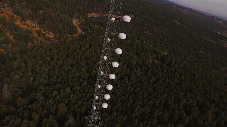
The DCR-M model is a center-fed, eight-bay antenna with an omnidirectional pattern. The antenna design has unique attributes to meet the weight and wind load limitations of our tower. A typical two-station antenna uses half-wavelength bay spacing, which would have required 16 bays to produce the appropriate antenna gain and 100 kW ERP with a 30 kW transmitter. The 16-bay antenna loading would not have been a solution for the current tower without significant tower modifications.
Dielectric solved this problem by spacing the antenna bays at an approximate 0.92 wavelength, which allows the 100 kW ERP to be produced with a lighter eight-bay design.
Dielectric’s “funky elbow” design maintains the full-wavelength electrical spacing between the antenna bays while allowing the physical spacing to be reduced, resulting in near full-wavelength bay spacing antenna gain. It also simultaneously reduces the RF radiation on the ground, which was a concern given the tower’s proximity to walking trails, campsites and wildlife.
The antenna also includes a “fine matcher,” which allowed for easy adjustments of the antenna system’s input impedance upon installation on the tower.
Galvanized Endeavors of Colorado Springs handled the DCR-M installation, as well as removal of the old antenna and damaged transmission line. The new antenna mount and transmission line were put into place, and the antenna was installed on the tower with its center of radiation positioned at 163 feet above ground level.
Given that the site elevation is at 8,350 feet above sea level, the antenna is prone to very heavy winds (often above 100 mph) and a consistent 20-to-30-inch snowpack in the colder months.
These weather conditions truly require antenna protection, and Dielectric’s antenna radome design has already delivered. We experienced a hefty snowstorm in October, which left several inches of ice and snow on all surrounding structures. The antenna was white from top to bottom, yet the radomes offered full protection from the wintry conditions. The antenna remained in tune, and with no change to VWSR levels, which remained steady between 1:05 and 1:08 across both station frequencies.
Inside the transmitter building, the Dielectric two-station combiner is properly matched to both the transmission frequencies and the transmitter power output. This means the combined signals are sent to the antenna with the right amount of power with minimal loss and a proper safety margin — all while meeting the mask requirements. The combiner properly prevents intermodulation issues from the two signals mixing along the path.
Even though the transmitter site’s mountain elevation required the RF components to be derated for altitude, Dielectric’s modern combiner design is compact, and the new system opens up a great deal of interior building space.
As this is a shared space, floor space is at a premium. The new combiner fits comfortably in the building, which allows us to make the most efficient rigid transmission line run possible — a perfect convergence point with the antenna feedline coming into the building. The location of the combiner means I can access the rear of my transmitters and audio racks comfortably to perform maintenance.
Two months in, the new Dielectric system has exceeded our expectations performance-wise, while providing a robust and reliable solution which has simplified our lives in engineering.